14 · Parameters
Parameters
Isolation, drilling, cutout, safety heights, solder-mask and silkscreen settings.
Copper isolation
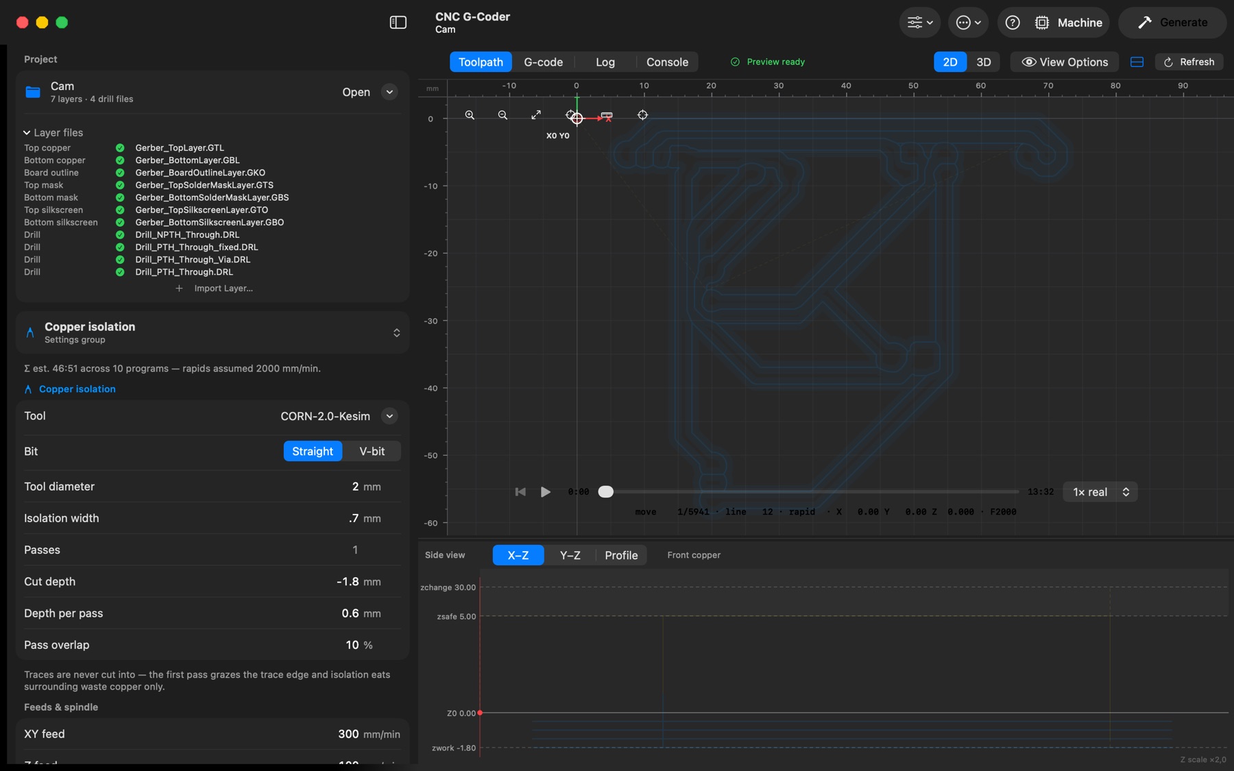
- Tool diameter — the effective diameter at cutting depth (see "Tools & V-bits" above), or pick V-bit and enter tip + angle.
- Isolation width — total copper cleared around each trace; machining time grows almost linearly with it. 2–3× tool diameter is a good start.
- Cut depth — copper foil is ~0.035 mm; −0.05…−0.08 mm cuts through with margin. Deeper widens V-bit cuts and thins traces.
- Depth per pass — reach the cut depth in several equal passes of at most this depth. 0 = one pass.
- Pass overlap — overlap between neighbouring isolation passes (default 50%).
- Traces are never cut into: the first pass is offset outward, isolation eats surrounding waste copper only.
Drilling & cutout
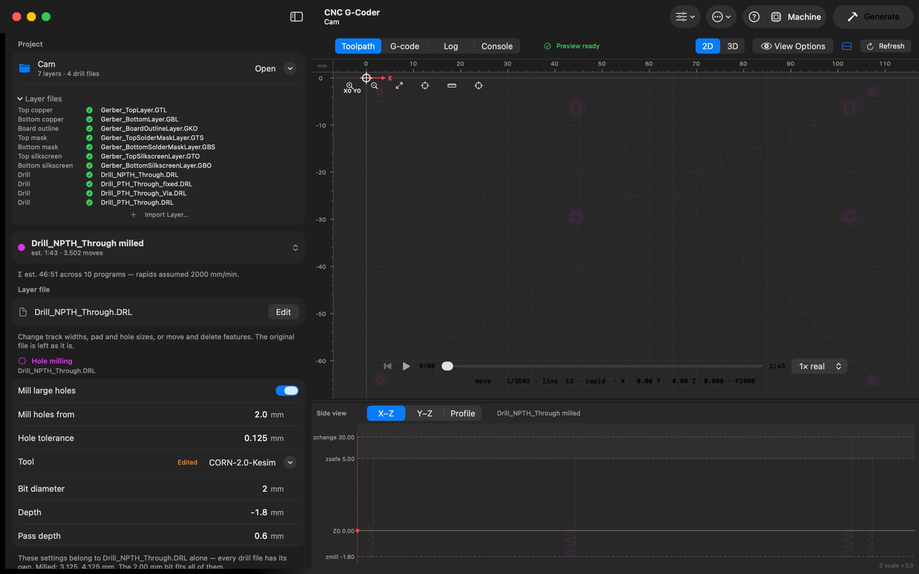
- Every drill file has its own settings. Select a drill program (or its
… milledprogram) and the Drilling, Bits on hand, Hole milling and Heights & direction groups show that file's values — the header names the file. Turning on Mill large holes for the NPTH file, or giving the via file a shallower depth, changes nothing for the other drill files. A file added to the project starts from the drilling defaults (shown when no drill program is selected) and keeps its own values from then on; they are saved in the project with the file. Applying a preset puts every drill file on the preset's values. - Depths = board thickness + ~0.2 mm into the spoilboard (1.6 mm stock → −1.8).
- Peck depth — drill in pecks: after each one the bit rapids out to clear chips, returns to just above the previous bottom and feeds on. 0 = one stroke.
- Bits on hand — one row per hole size of the drill file: the designed diameter and the library drill that drills it. The menu offers the drills whose range covers that size (closest at or above first, with its changer slot when loaded), Other drills for anything else, and Drill at the designed size for no bit at all. Mind Hole tolerance above: it enlarges every hole before a bit is matched, so a 1.0 mm drill (holes 0.90–1.10) does not take a 1.0 mm hole drilled at 1.125 — the row says so; set the tolerance to 0 or pick a wider drill. Pick bits for every hole chooses one for each size in a click; Use the changer's drills (Carvera) lets the loaded drills take the holes they cover; a drill picked as the group's Tool counts as a bit too. Every hole inside a chosen bit's range is drilled with that bit, so a job needs only those bits (a 0.915 mm hole goes to the 1.0 mm bit); bits without a range of their own use Bit tolerance (± around the bit). Holes with no bit keep their designed size and the Log names them — ranges are always passed, because without them pcb2gcode would round every hole to the nearest bit (a 3 mm mounting hole silently drilled at 1 mm).
- Hole milling — for holes bigger than any drill you own (e.g. 3–4 mm mounting holes with a 2 mm 2-flute corn bit). Turn on Mill large holes; holes from Mill holes from up are not drilled but cut in circles, spiralling down (helical G2 moves), into a separate
… milledprogram run right after its drill program. The hole-milling bit has its own Tool menu (cutout and general tools from the library), diameter, depth, pass depth (per turn of the spiral), feeds, spindle and dwell. The circle is offset inward by half the bit, so holes come out at their designed size; the bit must be smaller than the smallest milled hole. - The cutout runs laps of Pass depth; time = laps × perimeter ÷ feed.
- Bridges: on passes deeper than Bridge Z the cutter lifts and leaves holding tabs (white in the preview) so the board can't break loose on the final lap. Tab thickness = board bottom − Bridge Z. Snap and file after machining.
Safety heights & plunge clearance
- Safe Z — travel height between cuts; must clear clamps and board warp.
- Plunge clearance — vertical moves are rapid through the air and feed only below this height: descents rapid down to it then plunge at the Z feed; retracts feed up to it then rapid. This often halves program time (pcb2gcode alone feeds the whole descent — and drill retracts too). 0.2–0.5 mm typical; must clear board warp; 0 disables. The bit always enters and leaves the material at the programmed feed.
- Milling direction (Machine setup) — Any lets pcb2gcode choose the shortest path; Climb or Conventional fixes it for every milling program (this turns off 2-opt path shortening, so programs get slightly longer).
- Rapid feed (Machine setup) — your machine's G0 speed, used only for the time estimates (FlatCAM's FR Rapids).
- Heights & direction (every layer; also stored per tool and imported from FlatCAM) — the layer's own Travel Z and Tool-change Z (the height for the tool-change pause and the end of the program; FlatCAM's Tool-change Z / End Z), left empty to use Machine setup's values, which show greyed in the field; Extra cut (isolation, mask, silkscreen and custom layers) — every closed contour runs on past its start by this length so no sliver is left where the loop closes; where pcb2gcode chains passes into one cut, the tool then retraces back along the groove, so only already-cut copper is cut again; Milling direction — Machine default or this layer's own; Spindle — clockwise (M3) or counter-clockwise (M4). Hole milling uses the drilling heights (it runs in the same pass).
- Spindle dwell (every layer, next to its spindle speed; also stored per tool in the library and imported from FlatCAM's dwell) — pause after the spindle starts, so it is at speed before cutting, and after it stops, before a tool change. 0 = no pause. pcb2gcode writes dwells in milliseconds (
G04 P2000), but GRBL and LinuxCNC read seconds, so the app writes each program's dwell in seconds (G04 P2.000). Machines configured for millisecond dwells (some Mach3 setups) need the value ×1000.
Solder mask etch
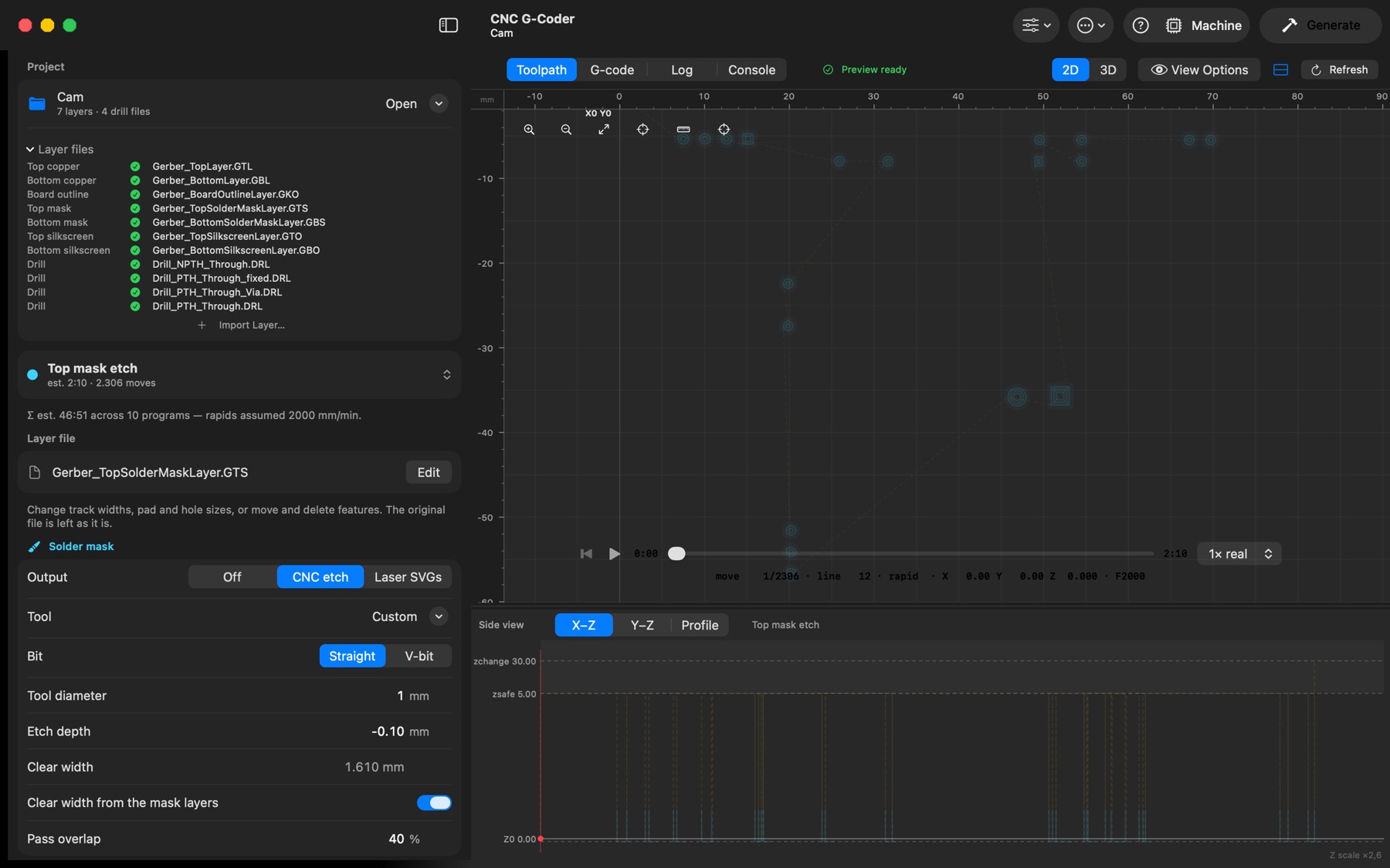
The .GTS/.GBS layers describe the openings (pads/vias that stay exposed). CNC etch mode inverts the layer and pockets each opening with 40% overlapping passes → top-mask-etch.ngc / bottom-mask-etch.ngc.
- Mask tool must be no larger than the smallest opening (smaller ones are skipped — watch the Log).
- Clear width — how far inward each opening is pocketed. By default (Clear width from the mask layers on) the app measures the widest opening in the mask files and clears by half of it plus a little, so every opening is cleared to its centre and no wider; the footer shows the widest opening. Switched off, enter it yourself: it must be ≥ half the widest opening or the middle of large openings stays covered, and larger values slow generation dramatically.
- Etch depth only needs to remove cured paint, not copper.
Silkscreen engraving
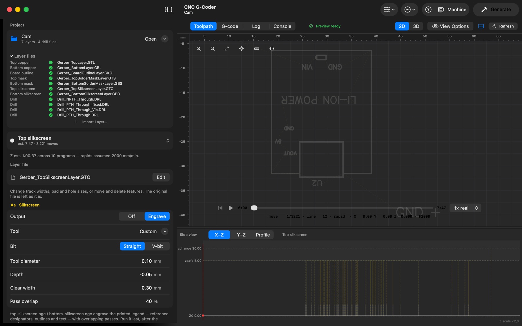
Silkscreen layers are off by default (engraving them costs generation and machining time). Output: Engrave mills the legend strokes themselves — reference designators, outlines and text — so they end up cut into the board: top-silkscreen.ngc / bottom-silkscreen.ngc, run last, after the mask. The section has its own tool (straight or V-bit), depth, Clear width (strokes wider than the tool are cleared with overlapping passes), pass overlap, feeds and spindle. Either way the layer can be exported to a laser once a program exists.
Feeds, spindle and per-layer heights
Every settings group ends with Feeds & spindle — XY feed, Z (plunge) feed, spindle speed and spindle dwell — and Heights & direction (Travel Z, Tool-change Z, Extra cut, Milling direction, Spindle direction), described under Safety heights & plunge clearance. Picking a tool from the Tool menu copies the library's values into the group; Edited appears when the fields no longer match the tool.