01 · Getting started
Workflow overview
The seven steps from a Gerber export to a finished board.
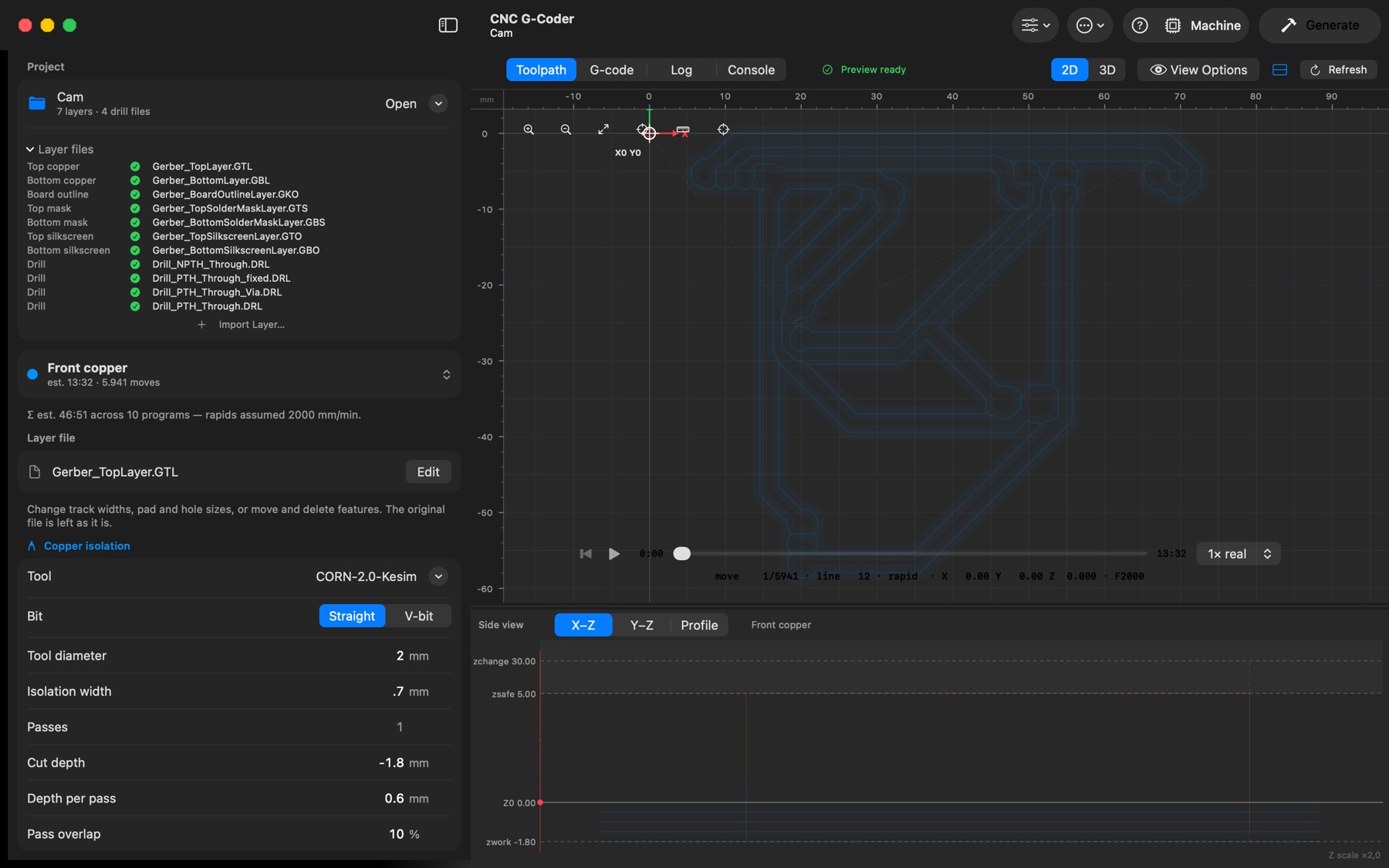
- Export Gerber + drill files from EasyEDA or KiCad into a folder.
- Choose Folder (toolbar) — layers are auto-detected by filename.
- Set your tools, depths and feeds (or load a Preset). The sidebar shows the settings for the selected program only — the layer menu at its top switches both the preview and the settings; pick Machine setup there for the parameters shared by every program.
- Inspect the preview: select each program, play it back, check depths in the side view and the total time estimate.
- Generate — pick (or create with New Folder) the destination folder; all
.ngcprograms are written there. - Machine in order: front copper isolation → drills (one program per drill file; change bits at the M0 pauses) → flip the board → back copper → outline cutout (bridges hold the board) → snap/file the bridge tabs.
- Solder mask: paint the milled board with UV solder mask, cure it, then run
top-mask-etch.ngc/bottom-mask-etch.ngcto mill the pad openings clear.
Using a laser engraver instead of (or next to) the mill: every program can also be exported as 1:1 artwork (SVG, PDF or PNG) — see Laser engraving & artwork export.