15 · Preview
Preview
The 2D and 3D views, the View Options and what their colours mean.
3D view
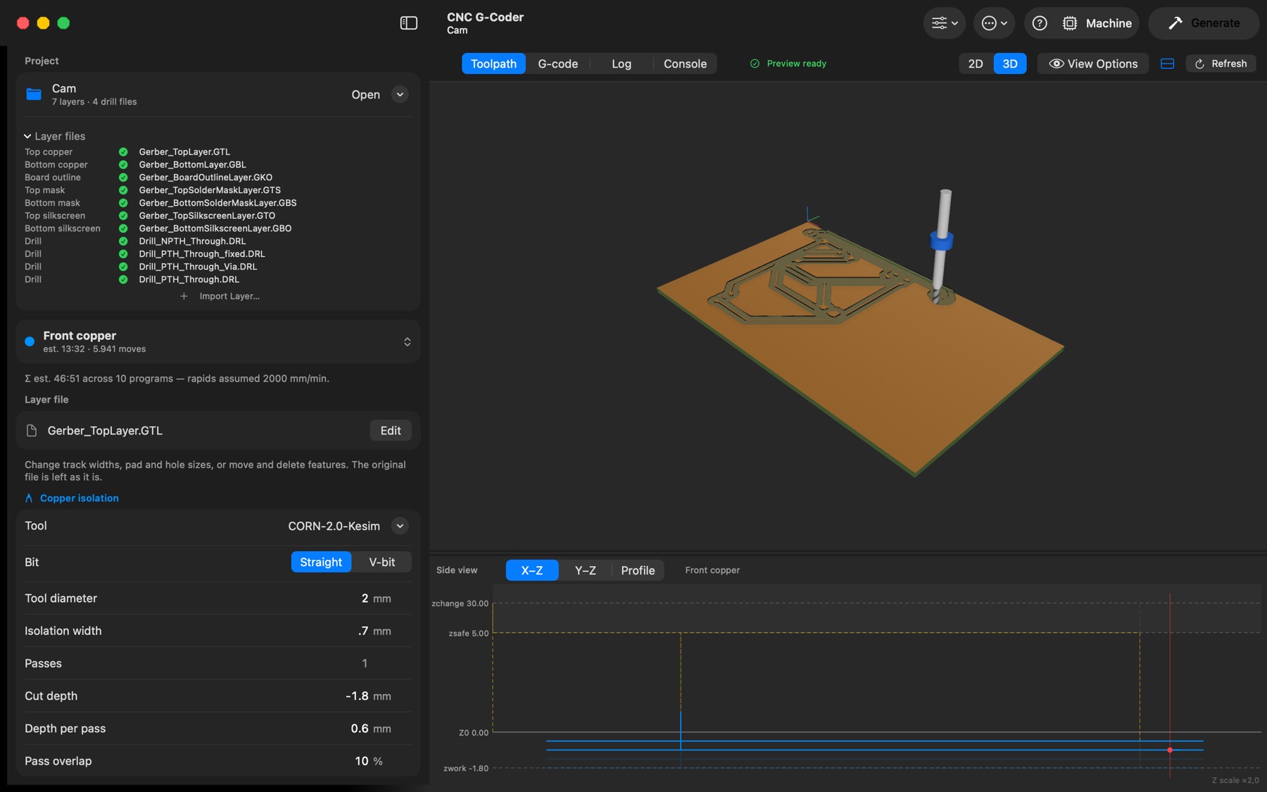
The 2D / 3D switch above the preview shows the programs in 3D: cuts as lines in each layer's colour, head travel in faint yellow above the board, and a translucent 1.6 mm FR4 slab sized from the cutout. Drag to orbit, right-drag or middle-drag (mouse wheel button) to pan, and scroll (mouse wheel or two-finger trackpad scroll) or pinch to zoom.
- Gizmo (top right): the X/Y/Z balls turn with the view; click one to look along that axis — Z = top, −Z = bottom, −Y = front, Y = back, X = right, −X = left. Below it: a menu of all standard views, Iso, Fit, perspective/orthographic, and travel moves on/off.
- With All Layers Overlay on, every program sits on the physical board: back-side programs appear un-mirrored on the underside, so you can orbit round to inspect the back. A single program is shown as it is machined.
- Playback works as in 2D: the finished part of the program is highlighted, and the bit that cuts the program follows the tool at real size — the V-bit's cone at its angle and tip, the end mill's or hole mill's diameter, a drill with its 118° point, all on a 1/8″ (3.175 mm), 38 mm shank with the coloured depth ring PCB bits carry (yellow V-bit, blue end mill, red drill, purple ball nose). It spins clockwise while the program plays.
- One program is shown at a time (layer menu at the top of the sidebar). All programs share one origin per side, so the "All Layers Overlay" registers copper, drills and masks exactly; enable "Un-mirror Back Side" to overlay the mirrored back side aligned with the front.
- Colors: per-layer colors for cuts; yellow dashed = head travel (no cutting); white = holding bridges; the translucent band under cuts is the real cutter width ("Tool Width" in the View Options menu).
- Un-mirror Back Side (View Options menu) un-mirrors back-side programs for visual alignment checks — display only; the G-code stays mirrored and CNC-ready. Off, the back correctly sits mirrored against the front.
View Options
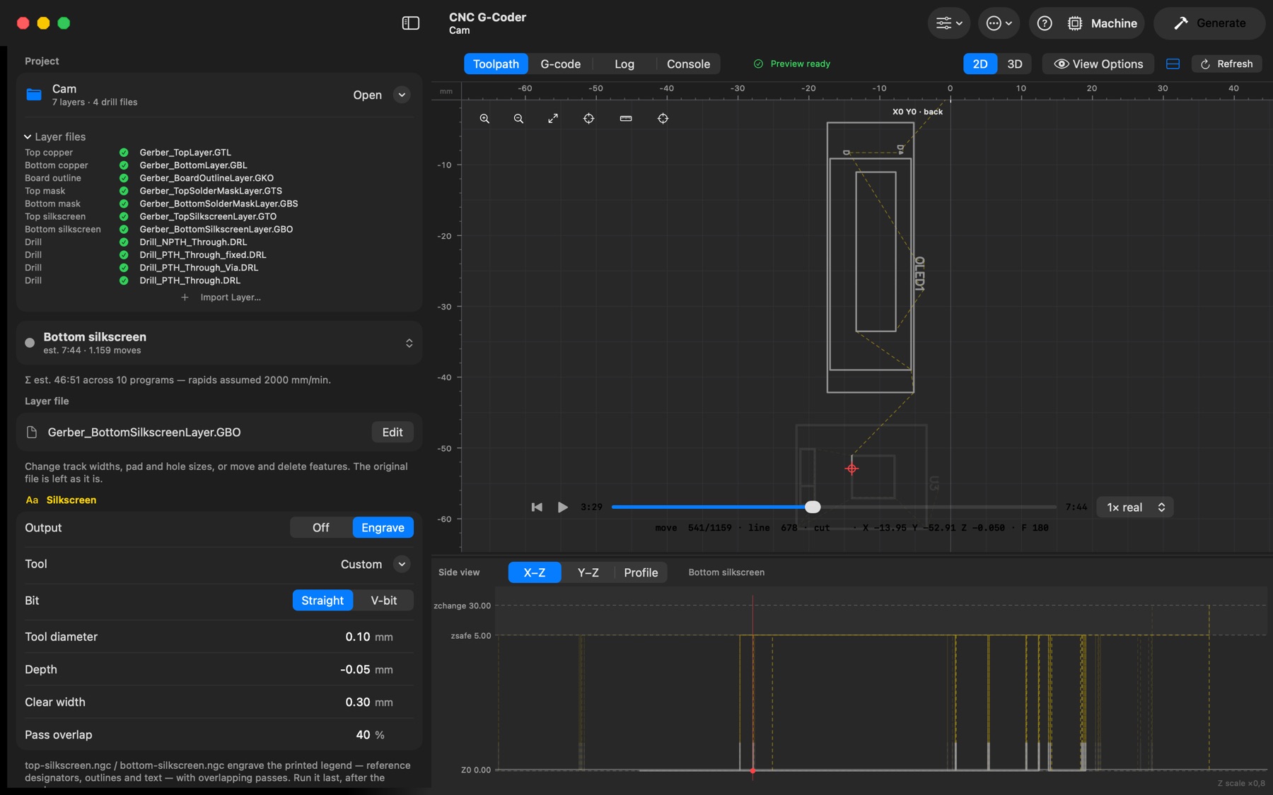
The View Options menu above the preview toggles what the views draw: Tool Width (the translucent band at the real cutter diameter; also decides whether a laser export is swept or centrelines), Rulers, Guides and Clear Guides, Snap to Grid (⌘'), All Layers Overlay, Un-mirror Back Side, Height Map with its exaggeration (×1 … ×50), Toolpath Lines, Drill Holes (the holes as cylinders in 3D), Material Removal (the cut channels and copper mask in 3D), Machine Travel (the connected machine's travel area, dashed) and Fit Machine Travel.
Guides. With Rulers and Guides on, drag out of a ruler into the view to pull a guide line; drag a guide to move it. Guides snap drawing, measuring and the origin marker, and are saved with the project. Clear Guides removes them all.
Canvas buttons (top left of the 2D view): zoom in, zoom out, fit (double-click does the same), set the origin by clicking, the tape measure, and centre on the origin.