04 · Getting started
Test boards
Three small boards that measure your setup: parameters, backlash, hole fit.
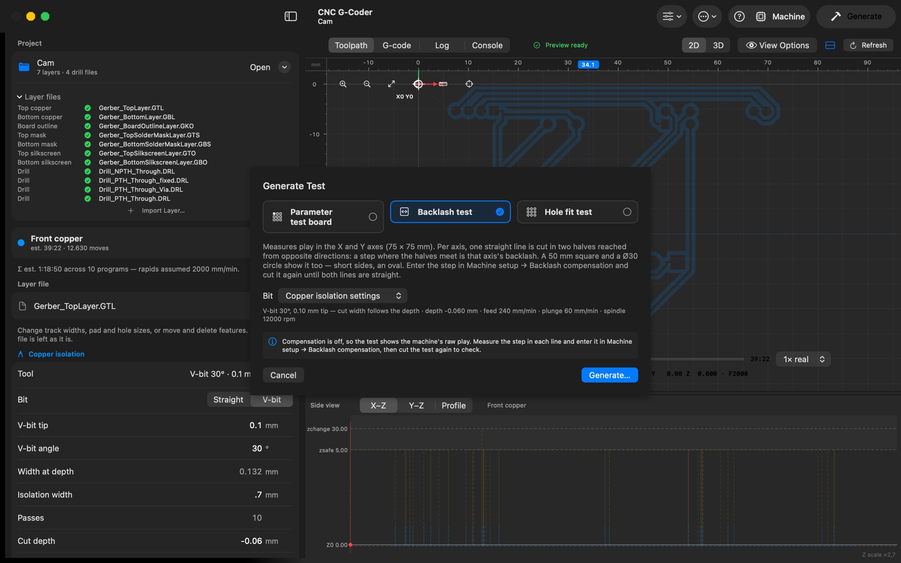
File → Generate Test Board… (⇧⌘T) cuts a small board that answers one question about your setup. Each test has its own bit (Bit, from the Tool Library; remembered per test — the default is the copper isolation bit, for the hole test the hole-milling bit) and its own settings; safe Z, plunge clearance and the isolation width come from the project. The result is written as a .ngc next to a legend .txt and shown in the preview like any program, so it can be played back and sent to the machine.
- Parameter test board — finds the cut depth and feed for production isolation. A grid of patches: rows sweep the cut depth (from … to), columns sweep the XY feed; each patch has 0.2 / 0.3 / 0.4 mm traces. Every trace runs between two probe pads inside a closed isolation moat, so a multimeter in continuity mode tells you whether the trace survived (pad to pad beeps) and whether the isolation is complete (pad to the surrounding copper stays silent). Board size and Grid (feeds × depths) set the layout; Suggest picks a grid for the board size. The legend maps each patch to its depth and feed.
- Backlash test — measures play in X and Y on a 75 × 75 mm board. Per axis, one straight line is cut in two halves reached from opposite directions: a step where the halves meet is that axis's backlash. A 50 mm square and a Ø30 circle show it too — short sides, an oval. Enter the step in Machine setup → Backlash compensation and cut the test again until both lines are straight (see Backlash compensation).
- Hole fit test — finds the hole size that fits a pin. Each hole size you list (rows) is milled in several variants (columns: the size plus a clearance in mm), the way production mills holes — a spiral down from the surface, then a clean-up circle. Push the pin into each hole of its row and keep the variant that fits the way you want; design the hole at that size. Mill it with the same bit as the real board.